
Technology Decoded: Hydraulic Brake System
Modified On Mar 09, 2016 03:31 PM By Sahib
- Write a comment
In hydraulic brake system, operating force applied to the brake pedal is delivered to the hydraulic unit which generates hydraulic pressure (using the Pascal’s law) for braking. Braking force is delivered to each wheel equally which leads to equal braking force among wheels and the system works fine even with a little brake effort.
Background/Development:
- Malcolm Loughead introduced the first concept of a four-wheel brake system using hydraulics in 1918.
- In 1921, Model A Duesenberg car was fitted with hydraulic brake system on all four wheels. The system was however had some leakage problems.
- During the 1930s hydraulic braking systems became standard fit on most cars.
Technology Explained:
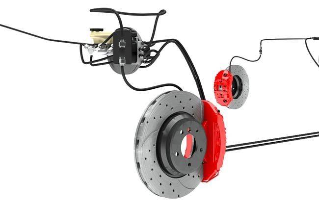
Hydraulic Brake system works on the principle of Pascal's law, which implies that the confined liquid transmits pressure intensity equally in all directions. This system consists of following main parts:
- Master Cylinder, which is connected to the four wheel cylinders through copper-coated, tin plated steel tubing.
- Rear Drum Brakes feature wheel cylinder (slave cylinder), which is used to expand the shoes against brake drum.
- Front Disc Brakes with caliper (cylinder body), which actually force brake pads to clamp the rotor and hence applies brake.
![]()
Other technical Insights are discussed below:
1. Master cylinder consists of reservoir tank which contains the brake fluid. This cylinder transmits highly pressurized brake fluid to all brakes by converting the effort at brake pedal into hydraulic pressure.
2. In case of 4 wheel brake system, Tandem type master cylinder is deployed which consists of two single single master cylinders mounted end to end and operated by same push rod and operate both the front and rear wheel brakes.
![]()
3. When the driver depresses pedal, the effort is transmitted through rod to piston 1 of tandem master cylinder.
4. The piston moves in the cylinder by compressing the return spring forcing out the fluid from the cylinder into brake line to apply front brakes.
5. At same instant, piston 1 also causes motion of piston 2 which pressurizes the fluid in 2nd chamber and forces it out of the cylinder into brake line to apply rear brakes.
6. In rear drum brakes, piston of a wheel cylinders are acted upon by the fluid. This fluid pressure forces piston to move forward and hence expand shoes against the drum.
7. Similarly, in front disc brakes, brake fluid flows to the cylinder body (caliper) and moves the piston which further makes brake pads to clamp the rotor and hence applies the brake.
HYDRAULIC BRAKE LINE LAYOUT:
![]()
Vapour Lock :
It is the condition when the oil in the brake circuit starts to boil and evaporate. Such condition leads to failure in transfer of oil pressure. As a result it can lead to transient loss of braking power or complete stalling. Main reasons behind Vapour Lock are:
- Use of foot brake excessively.
- Overheated by the drag of brake drum and lining.
- Poor oil quality or brake oil deterioration.
Watch this video for better understanding of Hydraulic Brake System:
Also Read: Technology Decoded: Disc Brake


")

")


")
")